A minimal guide to the use of CEDESK.
Getting Started
Pre-requisite
The software has been installed and configured. If not, see the setup instructions.
Rush Start
Once the application is launched, one can either open an existing project or start a new one.
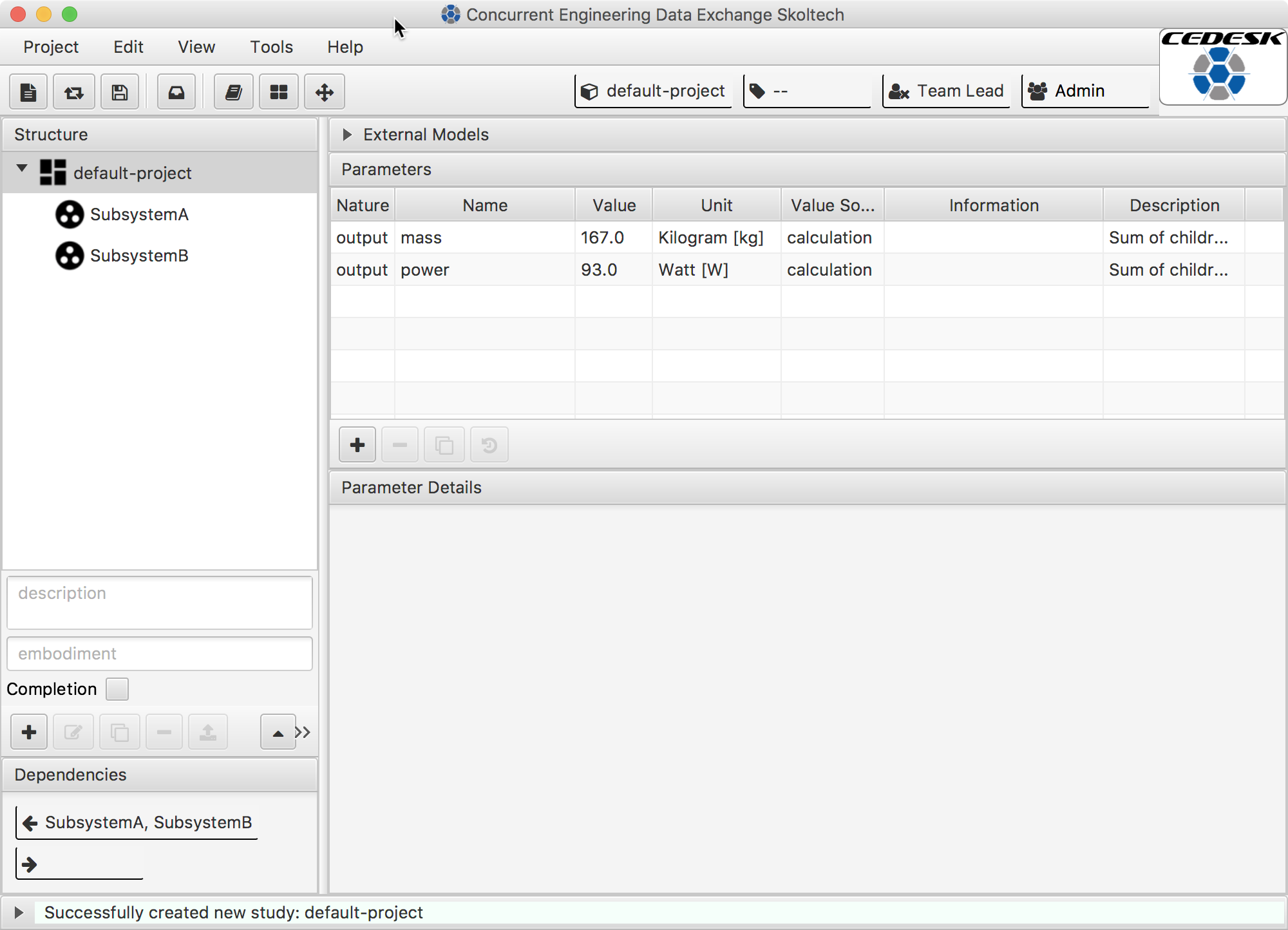
After creating a new project (menu Project -> New...), the application looks like the following screenshot, showing an interface for working on the system model.
Before working with the application it will be useful to go over the basic ideas behind it.
Basic concepts
Project the container of a design study.
System Model is the hirarchical structure of elements (also called model nodes). CEDESK supports 4 levels: 1) System, 2) Subsystem, 3) Instrument, 4) Component.
Model Node is an modelling entity capable to represent physical elements of a system e.g. Wheel), as well as logical elements (e.g. Communication) or disciplines (e.g. Thermal Engineering). See the structure tree on the user interface.
Parameter are entities to describe system elements attibutes (e.g. mass, power consumption). Parameters can have a description and unit of measure to document and communicate the meaning of the parameter.
External Model is the representation of model files (spreadsheet, script, drawing, etc.) made with third-party engineering tools. Currently (version 1.37) supported are: Text files (CSV), Excel 97-2013 workbooks (XLS, XLSX). Support for more kinds of model files is planned.
Discipline are used to assign users the permission to modify parts of the model (subsystem). The client offers an appropriate interface to make this user-discipline assignment.
Core concept: Parametric Models
Each model node encapsulates a parametric model, description of system configuration and behavior for sizing purposes at the stage of conceptual design.
Parametric models have input and output parameters, and contain some internal logics to map input values to output values.
Parameter Nature a parameter can be of nature: Input, Internal, or Output.
Value Source any parameter can have the value source Manual, meaning that the user sets the value, or Reference to take the value from an external model (e.g. a spreadsheet cell). Input parameters can receive their value from a Link to another’s model output.
Note: To speed up data exchange, CEDESK detects when an external model was changed (e.g. Excel file was saved) and updates the parameters which take there value from it.
Note: Whenever an output parameter changes, the parameters which link to it are also updated.
Primary Function: Building an integrated System Model
Similar to many collaborative design tools, with CEDESK, users load a project from the repository, operate on a local working copy, and store it back to the repository when needed.
At the top, the name of the current study, the logged-in user, and his active roles are displayed. According to the roles, a user is assigned; he can modify or only view a subsystem, its parameters, and external models. The user interface consists of four major parts enabling the user to work with the system model (see numbers in he following screenshot). 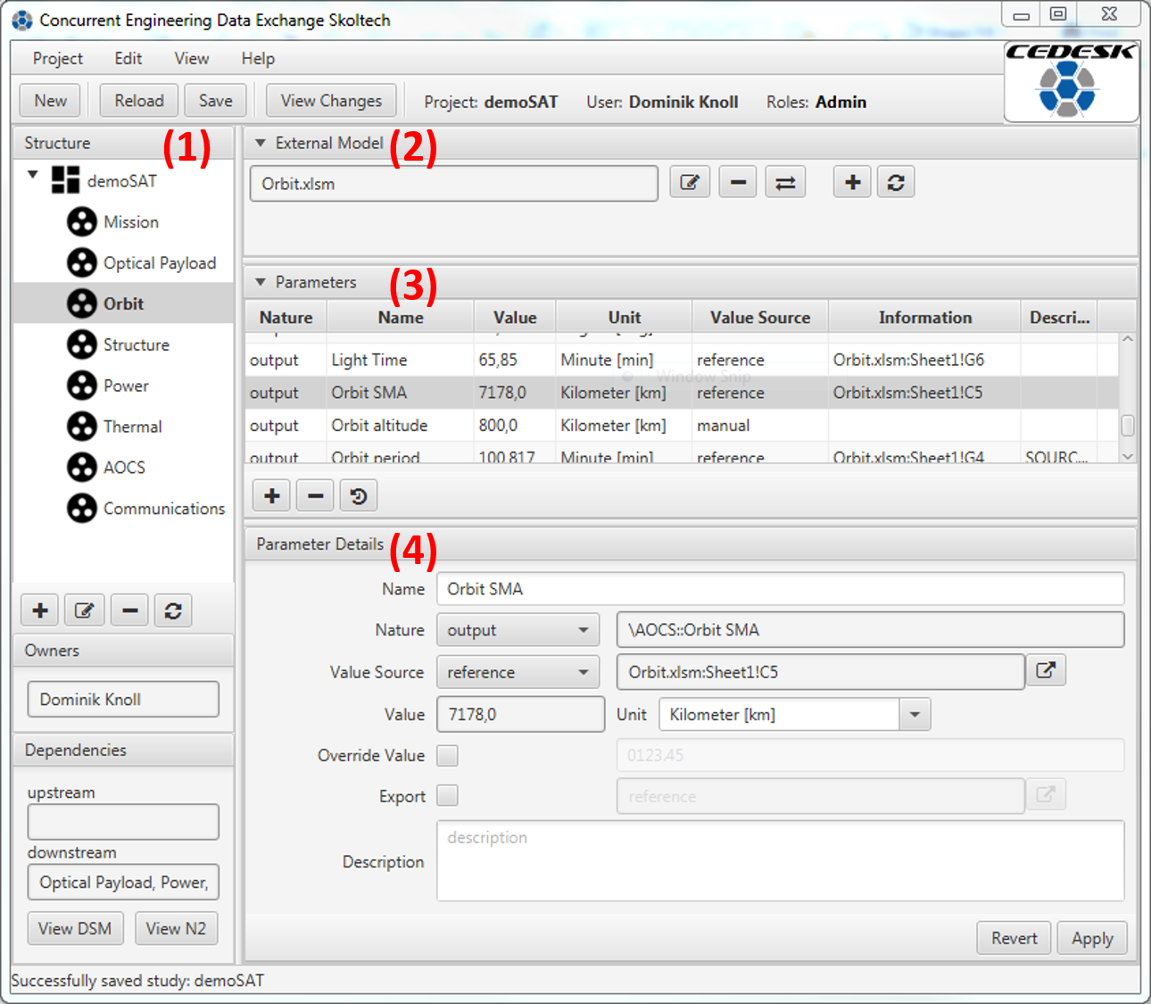
(1) A structure tree for the systems hierarchical decomposition. The buttons allow to add, modify, and delete model nodes. The screenshot shows the model of satellite “demoSAT” and its subsystems.
(2) A list of external models belonging to a model node. External models (files of third-party tools) can be attached, detached, and opened with the respective tool directly from there with the respective buttons. In the screenshot, an Excel workbook “Orbit.xslm” is attached to the subsystem “Orbit” selected on the left.
(3) A list of parameters belonging to a model node. The buttons on the bottom allow to add a new parameter, remove an existing parameter, and see the version history of a parameter.
(4) An area for parameter details, which also allows for immediate editing. In particular, this editor allows to create a link to another parameter or to set up the reference to external models. There is the possibility to clone a study by exporting the full system model to an XML archive and re-importing it with a new name. This can save the time for building the model for similar conceptual design studies.
A feature invisible to the user, but of interest to the researcher, is the logging of user activities, such as loading and saving the model as well as modifications to the model structure and parameters.
Modeling capabilities
The data model in CEDESK is structured according to ECCS-E-TM-E-10-25A, as much as it concerns parametric system models. The primary model entities represent the system structure, its parameters, units of measures, links between parameters, users, and roles. A study is composed of a system model, which is a tree structure of model nodes. A node represents the parametric model of and engineering discipline or a system component. Each model node contains a set of parameters and a set of external models. External models encapsulate files made by third-party engineering tools. Parameters can be of nature: input, internal, or output. Parameters have a value and can be associated with a unit of measure.
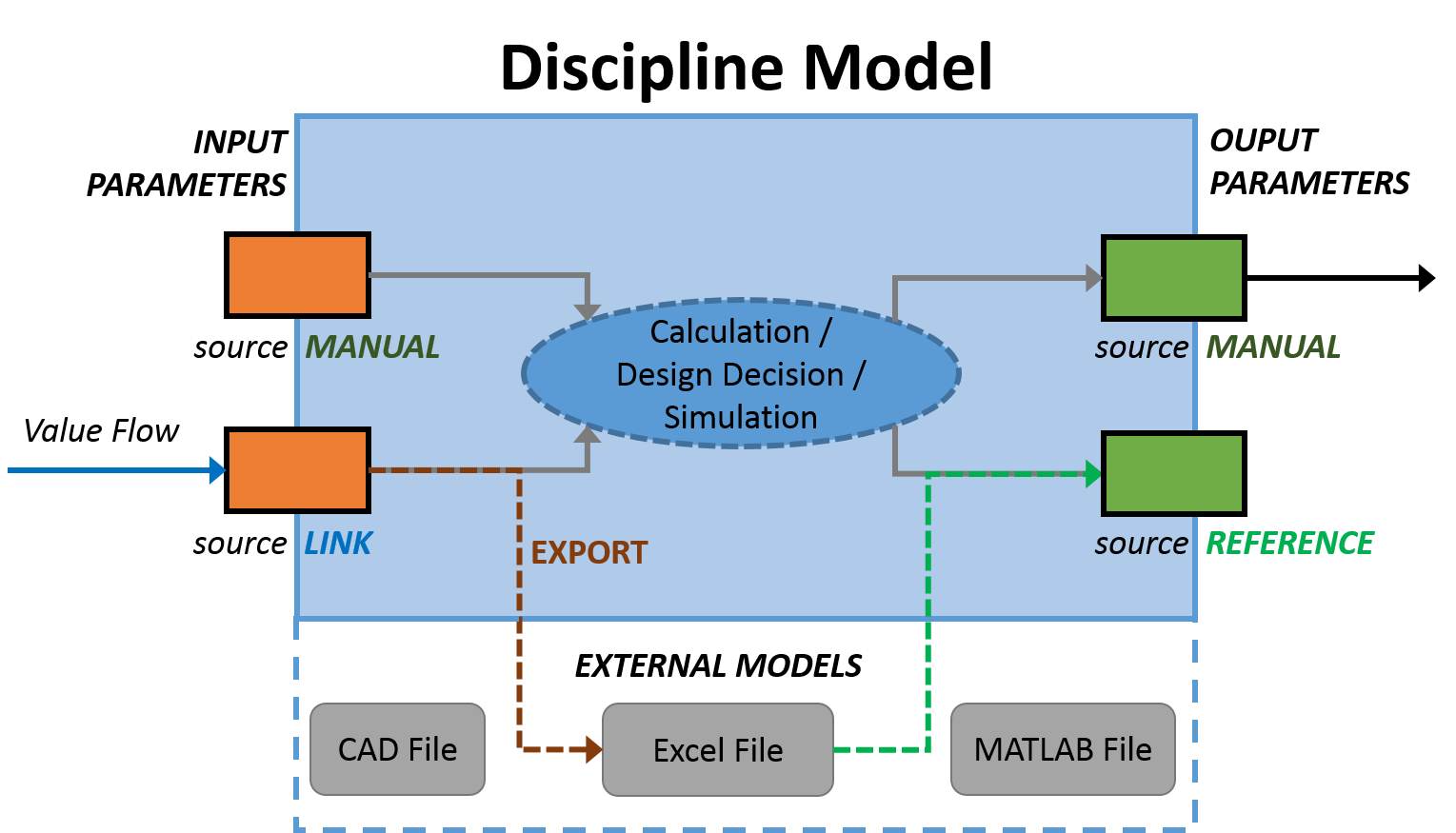
This diagram shows the structure and information flow in a parametric discipline model in CEDESK. This is how parametric models work in CEDESK: values of input parameters are fed into a calculation, a simulation or a human design decision and values for output parameters are produced. An input parameter can obtain its value either from manual setting or from a link to another subsystem’s parameter. Actually, only output parameters are visible to other subsystems and can be linked. An output parameter can obtain their value from manual setting or from a reference to an external model. In the example shown in the previous screenshot the parameter obtains its value from a reference to a specific cell from the Excel workbook Orbit.xlsm:Sheet1!C5. Whenever the value of a parameter is obtained from a link or an external model, there is an option to override the value. This is useful at the beginning of the concurrent conceptual design, when a discipline engineer works with assumptions before being provided with calculated values by another discipline. Finally, a parameter can also export its value to an external model (e.g. to a cell of an Excel spreadsheet).
Collaboration Function
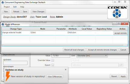
To enable multiple users work on a project, CEDESK also furnishes a user management and allows the assignment of users and roles. Fast turn-around in collaboration is facilitated by notifications to the user, whenever changes have been stored to the model repository. Changes made by other team members or the user’s own unsaved changes can be reviewed in a dedicated window. The screenshot shows a notification about changes made to the model by collaborators and possibility to review these changes.
For the purpose of access control, model nodes can be associated with roles, and roles associated with users. All changes to parameters are recorded and a full version history is kept. The data gathered this way can be used in future work analyzing of the history of design decisions using statistical methods for determining the sensitivity of design parameters. An important goal of CEDESK is to support the team leader in coordinating the design effort. A graphical representation of the dependencies is given in the form of an N-square chart. 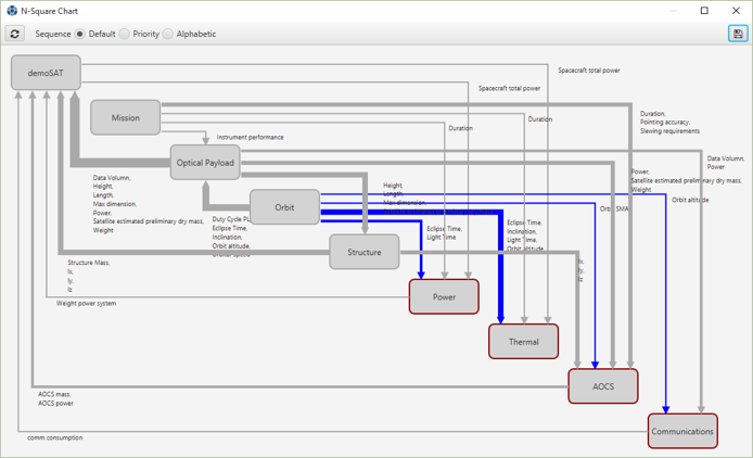
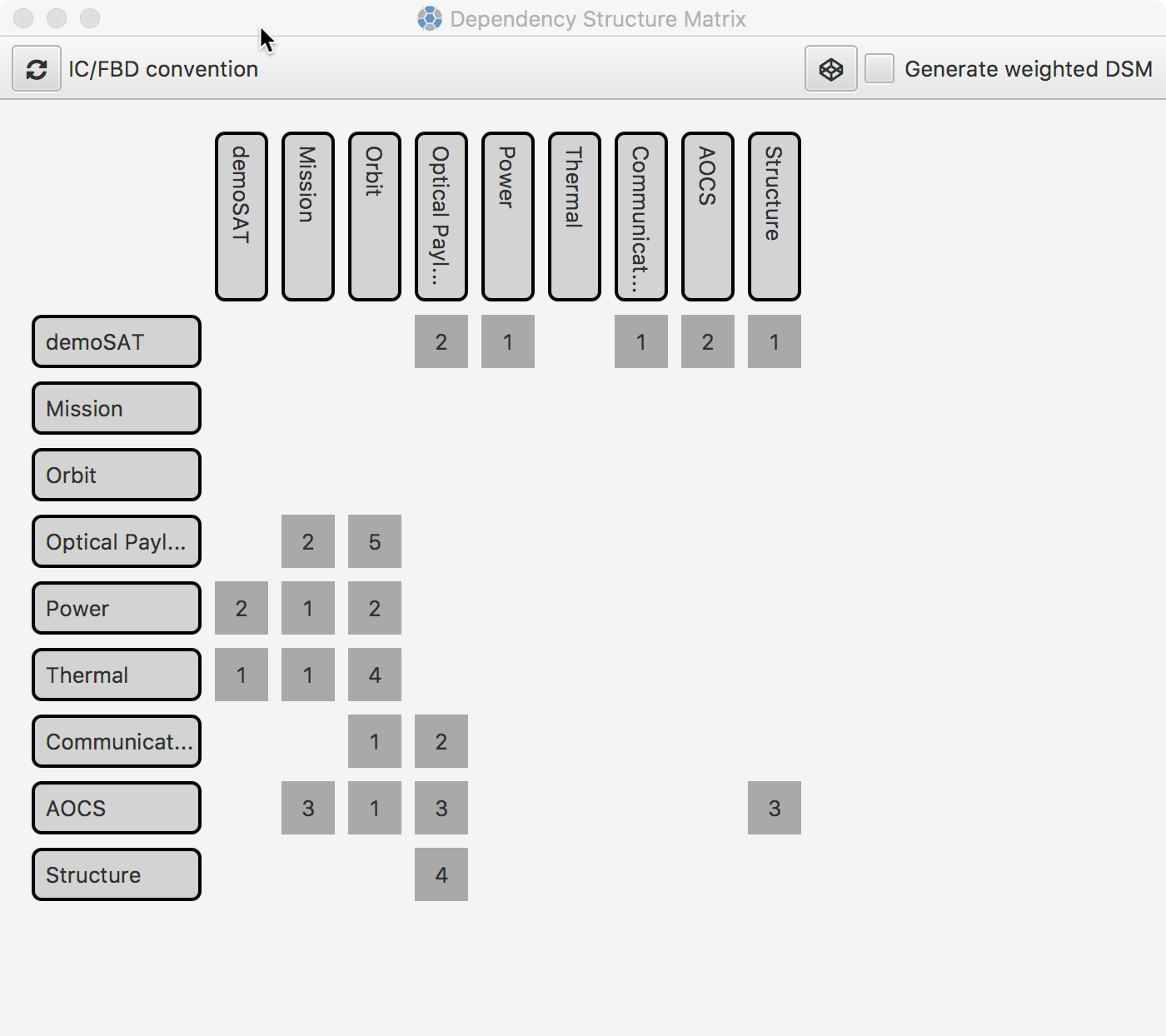
Another view allows to visualize the dependencies among subsystems in a DSM style. The cells of the matrix in list the names of the output parameters which pass values to other subsystems. The interface allows to run a DSM sequencing algorithm in order to provide the teamlead with a sequence in which to synchronize the disciplines that minimizes rework.